Adding Feed Rate Control to Ardiuno
Controlling A Solenoid Valve With Arduino
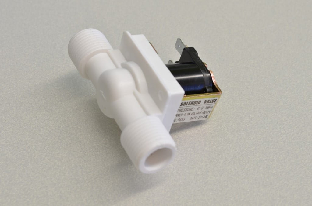
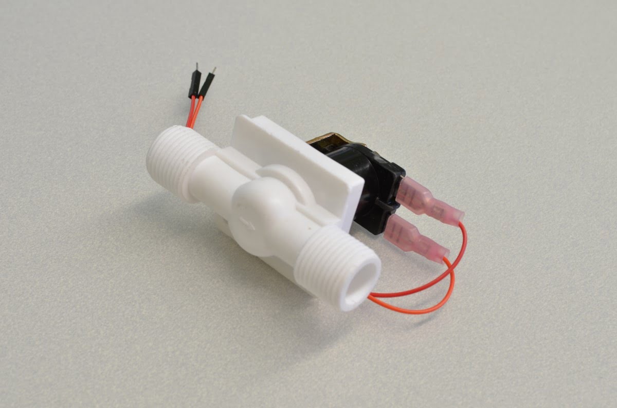
This solenoid does not have a wire harness and instead relies on 0.250″ Quick Connects. These are the best way to connect the solenoid. If you do not have Quick Connects laying around, Alligator Clips or even soldering wires to the tabs will work!
The connections on the solenoid do not matter, the coil does not care which side is positive or negative.
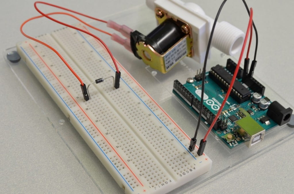
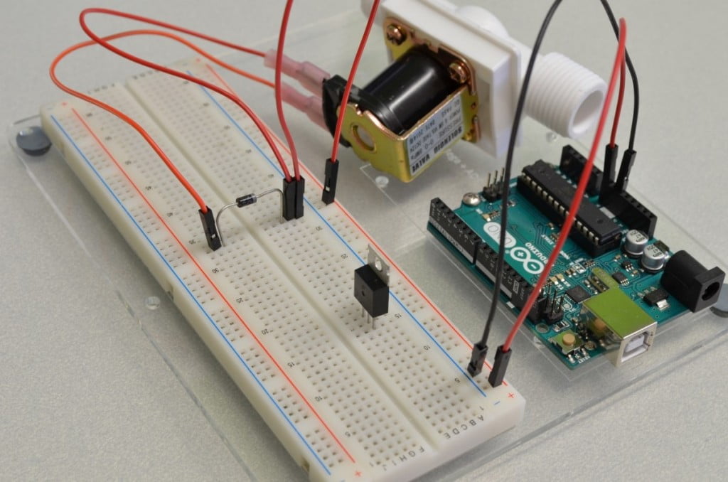
Since a solenoid is an inductive load we need to include a snubber diode across the contacts. Snubber diodes help eliminate transient voltages caused when a magnetic coil (such as those found in a motor, relay, or solenoid) suddenly loses power. Without this diode in place the transient voltage spikes can damage other elements of the circuit.
The snubber is placed from the negative side of the coil to the positive side. Since diodes only allow current to flow in one direction we need to make sure we get this right, otherwise it will be a dead short between power and ground. Ensure the side with the White stripe is connected to power/positive side of the solenoid! In our circuit the Red wire is the positive 9V so we will connect it to this side.
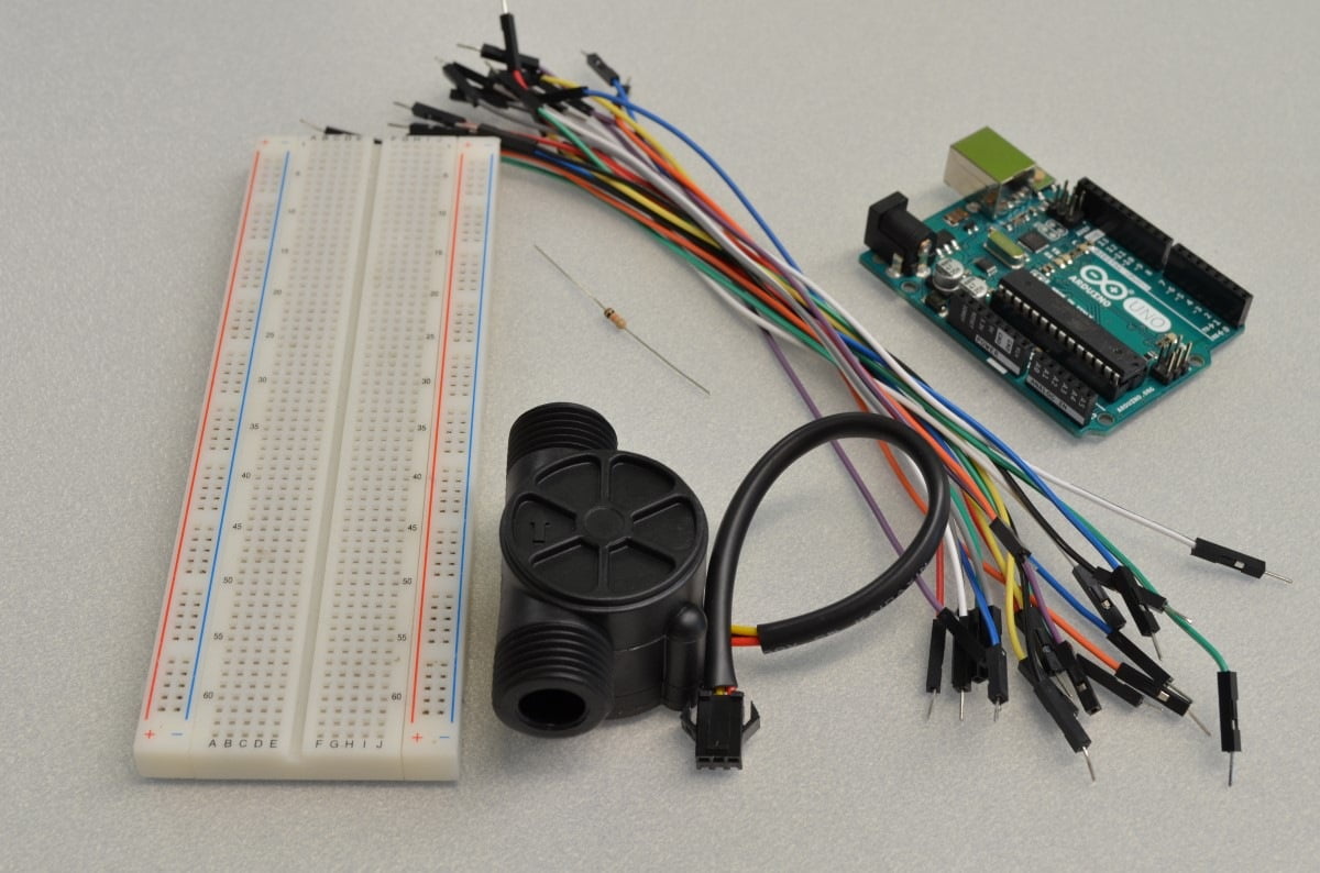
The current draw of this solenoid is higher than a standard transistor can handle so we will be using a TIP120 Darlington Transistor. A Darlington transistor is actually a pair of transistors that act as a single transistor with a high current gain. The pin output is still the same as a standard transistor so (for now) just think of this as a transistor with a higher current rating.
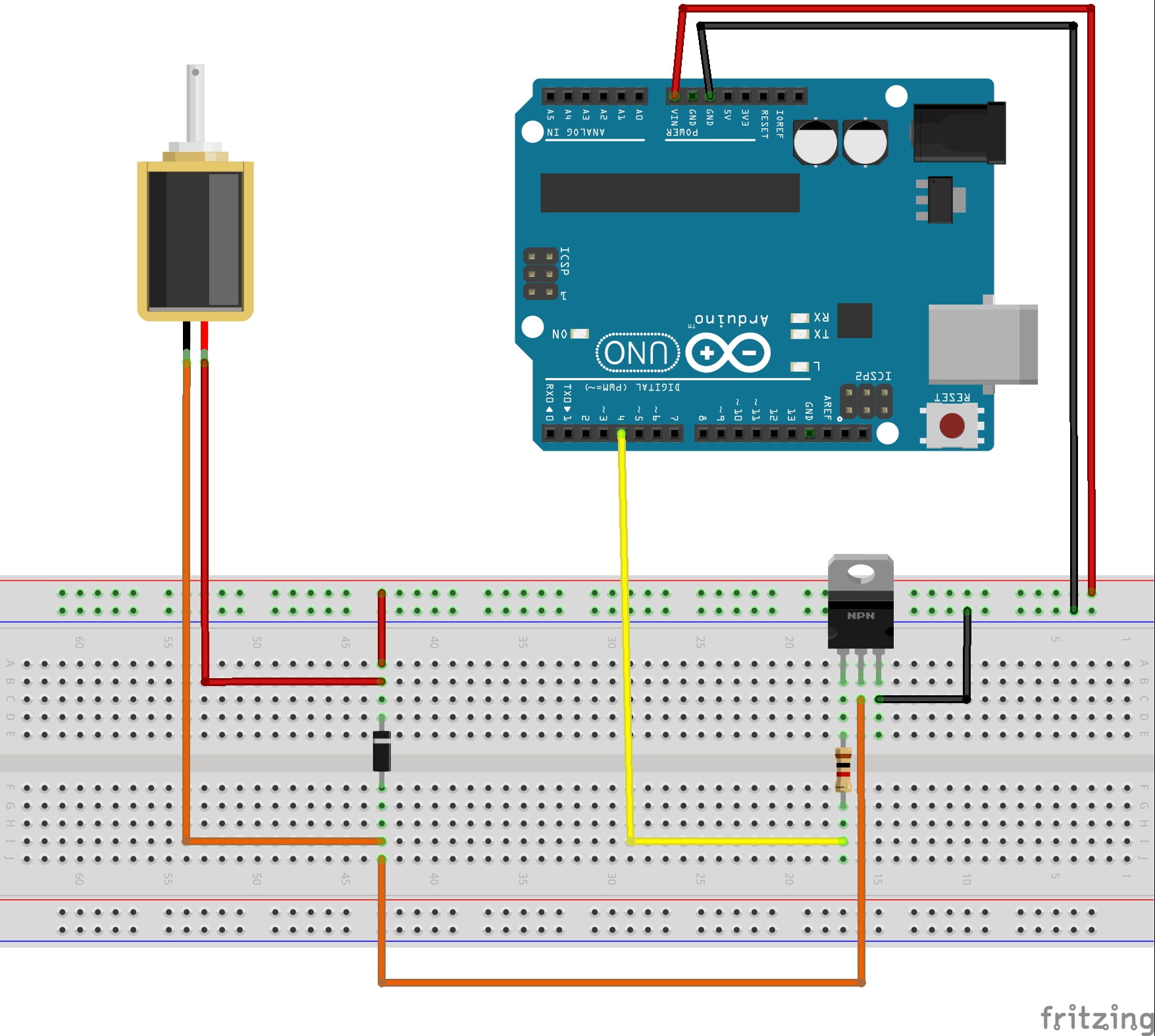
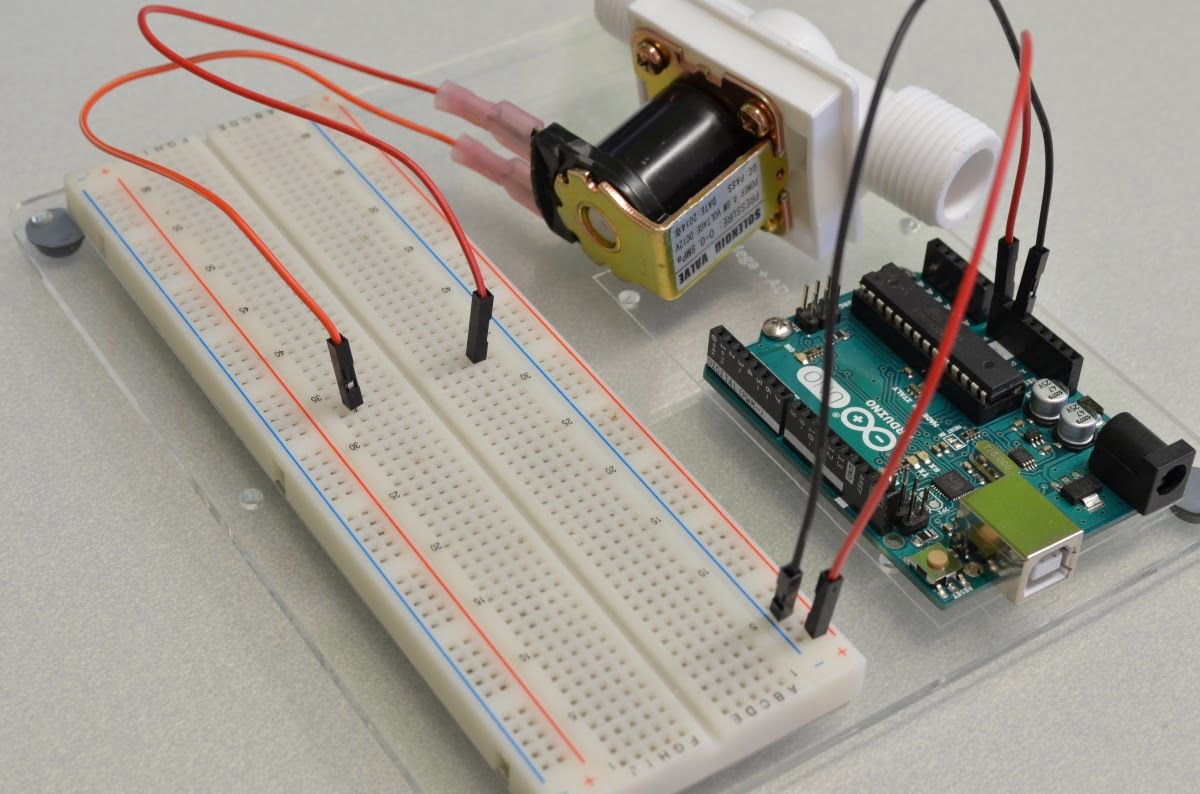
We will start by placing this transistor in the breadboard.

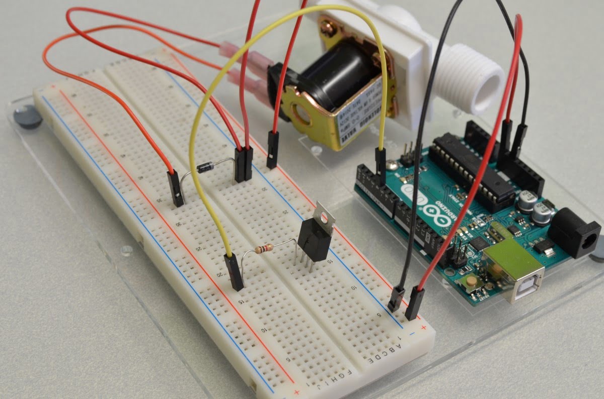
Next we are going to connect the solenoid's negative terminal to the collector on the transistor. The collector is one side of the "switch" in a transistor, this is connected to the emitter (other side of the "switch") when the base pin is has a voltage applied. An easy way to remember what goes where on a transistor is:
"The Collector collects whatever the Emitter will emit when the Base commands it to"
So in this case we are going to "collect" the negative from the solenoid and "emit" it to the ground of the circuit. So let's run a wire from the solenoid negative to the middle pin (collector) of the transistor.
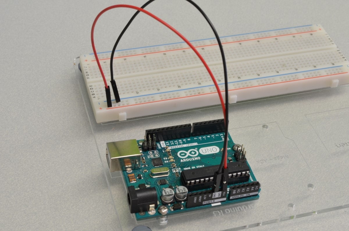
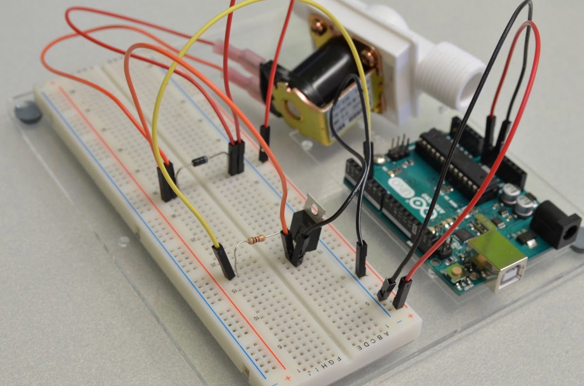
Before we give the Arduino power it is always a good idea to go over all of the connections to make sure there are no wires in the wrong spot – sometimes that can make for a very expensive mistake!
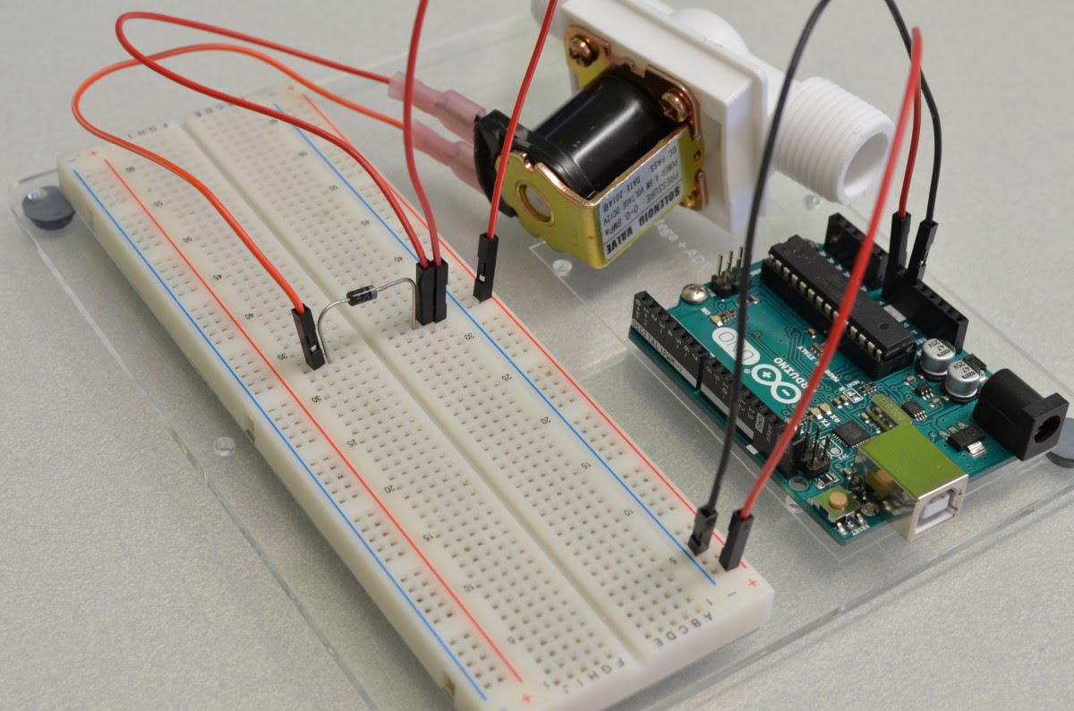
One way to avoid this problem is good wire color discipline. In other words, decide on a purpose for each color of wire and stick to them! In this example all 9V power are red wires, all grounds are black wires, orange is the negative output of the solenoid, and yellow is the signal wire. This way, if you ever see a red wire going to a black wire you will know right away that something isn't quite right!
void setup() { // put your setup code here, to run once: } void loop() { // put your main code here, to run repeatedly: } Now that we have finished with the hookup we need to start writing some code. We will be using the Arduino IDE, this is available from https://www.arduino.cc/en/Main/Software
We will start with the "BareMinimum" sketch found by clicking "File" and selecting Examples / Basic / BareMinimum. This sketch is a great starting point as it includes the Setup and Loop functions – we will write the rest!
Since the transistor is doing all of the heavy lifting in this circuit we do not need to do much in terms of coding. When Arduino pin 4 is set to HIGH this will connect the transistors collector to the transistor's emitter, which will activate the solenoid.
Let's go write the code!

183 thoughts on "Controlling A Solenoid Valve With Arduino"
Source: https://bc-robotics.com/tutorials/controlling-a-solenoid-valve-with-arduino/
mark
umm, i wanna ask… how about controlling 3 solenoid valve? can it still be the same way to control 3 solenoid valve? is there any other step to control 3 solenoid ?
can you help me solve this problem
Reply
Chris @ BCR
Hi Mark,
Do you have a link to the 3 solenoid valve? Without seeing it, it would be a guess… likely it would need the same circuit for each coil.
Reply
Jake
You could use a ULN200A Darlington transistor array to that project.
Hope this helped
Reply
mark
so, i have to make the other two solenoid into paralel?
every website/ link i have been seen .., they only control 1 solenoid valve
Reply
Chris @ BCR
Possibly – but if you have a picture we could answer that with a little more certainty 🙂
Reply
Matt
Could I separately power the breadboard (say 12v from a separate supply) and still do low side switching? I'm completely new to the world of electronics and don't want to destroy my Arduino from a rookie mistake. Essentially I wish to power several solenoid valves via the same breadboard and it would likely require more current than the Arduino can provide to the breadboard, hence the separate power supply.
Reply
Chris @ BCR
Hi Matt,
The pin we are using to bring power to the breadboard is labelled "VIN" and stands for "Voltage Input" on the Arduino – this is a direct pass through from the DC Barrel Jack on the Arduino. We used a 9V power supply in the tutorial but you can use a 12V power supply with that same DC barrel jack. Adding additional solenoid valves would not result in ruining the Arduino as you are directly powering the solenoid valves with the wall power supply already. Let us know if you have any additional questions!
Reply
Matt
Thank you so much for the quick reply!
The project that I have been thrown into would involves a logic system that would allow for me to have three solenoid valves open at the same time on timed intervals and remain open for a length of time. My concern is finding a DC barrel jack that would have the amperage needed to hold three solenoids open, especially since the system is gravity fed with negligible pressure resulting in (oddly, or so far as I can find) solenoids that require higher amperage to operate. For example I'm looking at 3 valves requiring 3 amps each to operate.
Assuming I could find a barrel jack power source with a high enough amperage to operate the valves (9 amps or greater), you're saying I could just use the VIN terminal instead of powering the board separately? And the wiring system used in this tutorial could be replicated three times (once for each solenoid) to operate the system? Excepting the coding of course which I have experience with.
Reply
Chris @ BCR
Hi Matt,
At 3A per solenoid you may want to take another approach all together. The solderless breadboard will not handle the total power of 9A, nor will the trace on Arduino. 3A per channel will exceed the capabilities of the TIP-120 as well. While there are better technical solutions to this problem – if you would like to build it on a breadboard I would recommend getting it all up and running with relays in place of the solenoids. The relays would act as on/off switches for the high powered solenoids. If you want to get in touch with us regarding the details of your project please feel free to email us at info@bc-robotics.com
Reply
Shawn
So an external power supply of 9v was used on breadboard all along? All along from my understanding i thought Vin from arduino would provide the 9v for solenoid valve. Please clarify this.
Reply
Chris @ BCR
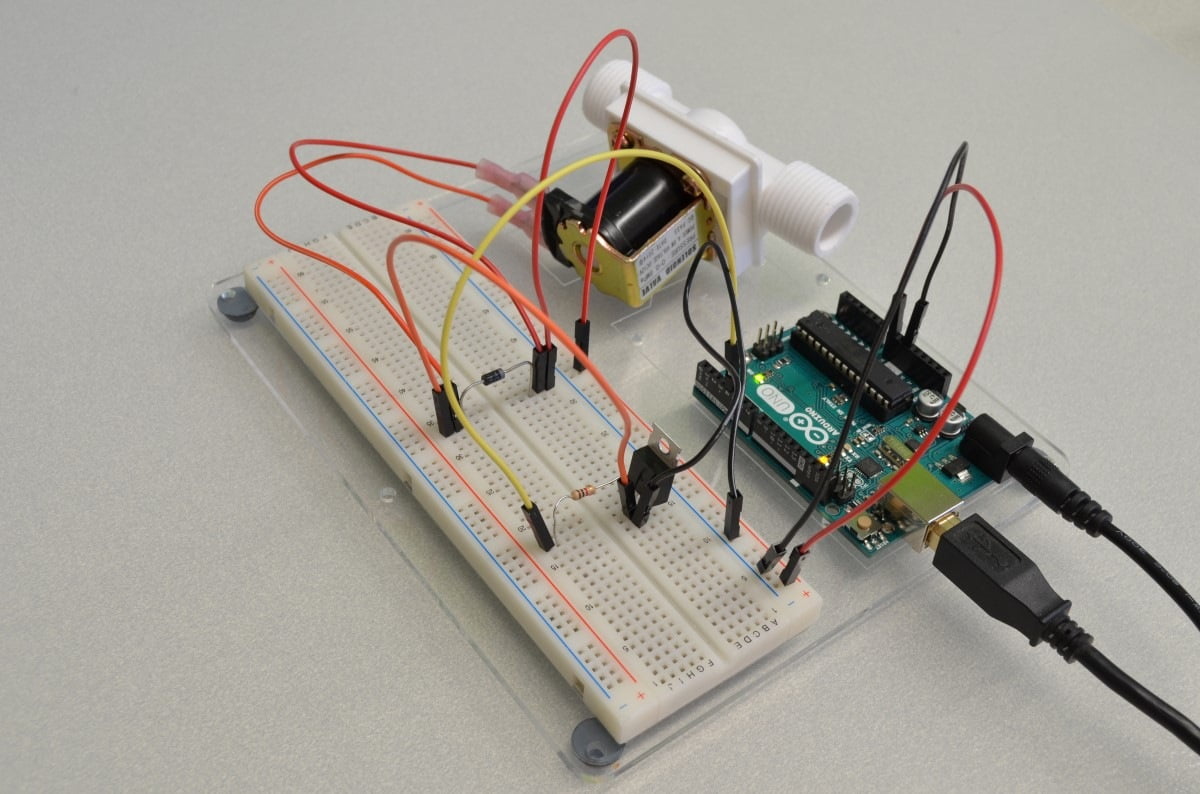
Ultimately, whether you supply the 9V through the breadboard or the DC barrel jack on the Arduino, the end result would be the same. In the last photo you can see we are using the 9V power supply in the DC barrel jack on the Arduino (and this is done simply out of convenience). If you were to feed 9V to the breadboard the Arduino would just be powered by the VIN pin rather than sending power to the breadboard by way of the VIN pin. The important thing to understand is that the VIN pin and the DC barrel jack on the Arduino are tied together directly; this VIN bus is also tied to the built in 5V regulator on the Arduino that powers the Arduino. As long as the VIN bus has 9V on it the Arduino should get its power and everything should work properly.
Reply
Bart Grefte
"The inlet water pressure actually holds the valve closed so if you do not have any inlet water pressure (3psi minimum) the valve will never close!"
Can you recommend a valve that does not have that limitation?
Reply
Chris @ BCR
Hello Bart,
We do not have a product without that limitation unfortunately.
Reply
Mike
Look into latching valves. They use a small current to open and a reverse polarity to close. You could open and close them one at a time.
Reply
Christian
This reply is very late but I use gravity fed solenoid valves for my projects without a significant PSI. You can find them pretty readily on Ebay. Hopefully this helps someone!
Reply
Marlo Kyn Bunda
I will be using 2 solenoids for our project. Do we need to have a relay or can we avoid using a relay? And how do we go about that? I am having challenges with connecting it to the breadboard.
Reply
Chris @ BCR
A relay would not be necessary unless the power requirements of the solenoid exceed the amount of power the Darlington transistor is able to switch.
Reply
Lionel Eisenberg
Hi Chris I have been trying to make the board work for some time now but for some reason im not getting any voltage, ie if i plug a voltmeter where the solenoid is supposed to be I get 0V could you help?
Reply
Chris @ BCR
Hi Lionel,
Please post (or send) us a photo of what you have so far!
Reply
Josh
Hello!! I have an Arduino Uno and a 5v solenoid. Is there any way I can power it without frying the unit? I am completely new to this kind of stuff and looking for any guidance on how to approach this. Thanks so much in advance!
Reply
Chris @ BCR
Hi Josh,
Rather than a 9 or 12V power supply, switch it out for a 5V supply to power the entire thing. The wiring will stay almost identical – just swap the red wire powering the Arduino from the "VIN" pin to the "5V" pin
Reply
Josh
Alright awesome, thanks for the quick reply. Would I need to change the type of transistor or diode? Thanks again!
Reply
Josh
ie; the transistor, the resistor, or the diode to a different p/n?
Reply
Mrunal Lalwani
A follow up to this, since Arduino Mega has four 5V pins, does that mean i can connect 4 solenoids to it? Or would I have to use another arduino?
P.S. Beginner in electronics, need this for a project.
Reply
Josh
Also, last question… I promise! If I have this 5v solenoid, https://www.adafruit.com/products/2776 … How would I connect the 2 pin to the breadboard? Alligator clips? I'm completely sorry but I have no idea how to work this!!!
Reply
Chris @ BCR
Hi Josh,
You would not need to change any of the components as the circuit is switching the ground. As for the solenoid – I would suggest using a chunk of wire just like they have done in the photo. If you do not need that connector on the end you could always chop it off as well.
Reply
Josh
Alright awesome, thanks so much again with help. My solenoid arrives Tuesday, so I will let you know how the setup goes. thanks!!
Reply
nagesh
I am using 24v solenoid water valve… but i am unable to connect to arduino uno as shown in this page wiring diamgram. Please advice whether i should used relay to connect 24v solenoid to arduino?
Reply
Ajay
Hi Chris,
I am using three 12v DC push pull magnet 7W for my project. I have hooked my arduino to big easy driver to control the stepper motor while on the other pins I'd like to control these 3 cylindrical magnets to go on&off for a period of time.
My question is should I use relay modules rated 5v –12v DC to control these magnets or should I go for transistor and diodes like you illustrated?
I'd be obliged if you can help me with my question.
Reply
Sergio
Hi, It's possible to control 100 solenoids? I'm a programmer and not electronic engineer :/
What changes would I have to make so 1 arduino could control 100 solenoids?
Thanks
Reply
Sabri
Hi, is this solenoid only match with TIP120 Darlington or can use others? Recently I used TIP42C, my program is not giving an output.
Reply
Chris @ BCR
Hello,
A TIP42C is a PNP Darlington, in this circuit you would need an NPN Darlington (So a TIP41C should work)
Reply
vwheatle
Could a TIP110 transistor also work? What is the current that the solenoid will draw?
Reply
David
Hey guys,
I have a similar issue to some of the above comments, have read through them but am still unsure due to my inexperience.
I'm trying to operate 5 different 12V water solenoid valves through a Arduino Uno. How would I go about powering this kind of project? Obviously once the powering and layout is done I'm assuming the code is just like the one showed, so i'll keep my question simple 🙂
Thanks in advance!
Reply
Chris @ BCR
Yes, you would power it the same as above – the diagram above will handle as many solenoids as you have IO pins available.
Reply
Adi
Thanks for your awesome tutorial. I'm totally new to arduino. 😀
Quick question here, can I use Vin pin to power a solenoid as in your tutorial while at the same time using the 5V pin for another purpose?
Big thanks!
Reply
Chris @ BCR
You can still use the 5V pin because it is pulling power off of the 5V regulator on the Arduino *but* I wouldn't be powering anything too power hungry with it. You can always use something like an LM7805 to create another 5V source on the breadboard.
Reply
mahesh
Great tutorial. . Finally everything is working .. I added few switches to control flow etc …
I used uno r3 .. plan to go for yun as it can connect to AWS IOT ..
However found that yun does not have DC input. So how will circuit look like with yun .. will I need a relay .. or can I still use transistor approach .. hard to digest if I can not use this thing ..
Thanks
Reply
Chris @ BCR
Hello,
With the Yun you would need to add in a 5V regulator on the breadboard to feed the Arduino. Alternatively you can power the Yun from a separate power supply as long as you tie the grounds together.
Hopefully that helps!
Reply
Sanjeev Kumar
on Yun you can power it from VIN pin on the analog side.
Reply
Arnav Raj
Can I power the solenoid by using only the USB connection in arduino.
Reply
Rcname
How I power the selenoid then?
Reply
sapwood
for the next person that reads this, you use a 5v or 12v dedicated power supply for the arduino and use the VIN pin location to supply that voltage to your circuit. if you use a 12v power supply the arduino steps it down for itself and passes the 12v around to the VIN pin…
or so i think that's how it works
Reply
Cameron James
To whom it may concern,
I am working on an Arduino project that incorporates both a solenoid valve and a liquid flow meter, which I want to have activate at the same time. I viewed the tutorials for each of these on the BC Robotics website, and I noticed it was mentioned that these could be easily used together. Any help or guidance with how wiring would work to operate both of these at the same time would be much appreciated. The solenoid valve and liquid flow meter I will be using can be viewed in the links below:
https://www.adafruit.com/products/996
https://www.adafruit.com/products/833
Thanks
Reply
Diego Garcia
Thanks for the tutorial.
I am having a little trouble with it however.
I have done everything correctly including the code but the solenoid valve wont open.
I used a voltmeter to make sure I was getting current at the valve and I am, but just around 6 volts.
The battery is brand new so I don't now why the voltage is that low at the valve.
Any help would be appreciated.
Reply
Diego Garcia
Also when I disconnect the usb from the Arduino, I will only get a current for an instant and then nothing at all.
Reply
mike87
what is the battery rating?
Reply
Luke Harrison
Hi, friends and I working on getting a solenoid valve to work for a school project, and we have done everything according to your tutorial and it doesn't work.
The valve only opens when we blow to create pressure, otherwise no amount of water in a tank (that is directly connected to the valve) is able to open it.
We tried connecting the power to 5V but it made no difference.
We would greatly appreciate your help,
Reply
Chris @ BCR
Hi Luke!
The issue is likely not with anything you have wired or programmed – the valve we carry needs minimum of 3PSI of pressure to open.
Reply
Adam Goodman
You would need 7ft of water level above the valve to create 3psi of pressure at the valve.
Reply
Ash
Hi there, thank you so much for this tutorial, it is very informative.
I was wondering, for my project, I need to connect a 24V solenoid valve to Arduino, is that possible? what modifications would I need to make to the circuit or components (diode, transistor,resistor)?
Reply
Chris @ BCR
I would first check and see if 12V will trip the solenoid reliably… if so, just do that!
Otherwise the biggest thing you need to worry about is powering the Arduino. The easiest way would be to power the Arduino from a separate power supply. Everything else will tolerate the 24V power.
Reply
Robert Kipngeno
Hi what of air tight solenoid valve? Does it use the same circuit ,do you stock them and how much are u selling ?
Reply
Greg
Greetings,
How close does the solenoid need to be to the board. I am putting this in a high tunnel and will have to protect it from the elements.
Thanks,
Newbee
Reply
Chris @ BCR
It doesn't need to be that close – but ultimately it will have more to do with the gauge of wire than anything else.
Reply
Yossi
Thanks for the tutorial!
Is is possible to to turn on and off the solenoid only with a relay board?
If yes i would like to know if needed yo add diodes or resistors?
If not i would like to know why?
Thanks for your help
Reply
Chris @ BCR
In theory you could use a relay – the only reason to do this would be if the Solenoid is powered by a different power source (Either AC or higher voltage, etc). As for the additional components: whether or not they are needed and the type of component needed will always depend on how you are hooking it up and how you are powering it – there is no generic answer.
Reply
Victoria
Hello. I used a solenoid directional air control valve instead of the the same solenoid valve that you used and did the same connection. I could see the LED light inside turn on/ off but the valve itself was not open/ close properly. Do you know why? The solenoid I used is 12V rated. Thanks a lot.
Reply
Chavi
Hi,
I have a solenoid that's not close automatically, then I need to invert polarity to close, I tried with an H-bridge but it's not working. If I follow the tutorial and I change the wires the solenoid opens and closes correctly. Why it's not working with an h-bridge? and what can I do?
Thanks!!
Reply
Chris @ BCR
The H-bridge is probably the best way to approach it – We will have a tutorial for using an H-bridge coming up soon. In the mean time I would suggest throwing a motor in place of the servo and see if it works in both directions.
Reply
Hafiz
Hi Chris,
Thanks for the tutorial. Is there any way that I can control 2 solenoids at the same time?
Reply
Chris @ BCR
The easiest way to accomplish this would be to parallel the entire circuit, and just connect the base of the transistor to another one of the Arduino's digital I/O. Just modify the code to trigger the correct valve at the correct time and you should be good to go!
Reply
sidrah
I'm quite new to coding, so how would I modify the code to trigger the correct valve. Would be great if you could reply
Reply
babak
hi, would like to know what is the maximum length of wire i can hook up to this solenoid to work with arduino?
Reply
mike87
It depends? What is the input voltage tripping the solenoid, the linear resistance of the wire, the ambient temperature, current draw of the solenoid, trigger voltage of the solenoid, and so on.
Reply
Abhirup Das
I think a mistake has been made.
In Step 9. The last paragraph.
You have written.:"So let's run a wire from the solenoid negative to the middle pin (emitter) of the transistor."
The term in brackets should be "collector" in the middle pin of the transistor.
Great tutorial tho for a beginner. Cleared lots of queries! 🙂
Reply
Chris @ BCR
Thank you for pointing that out, it is a good catch! We have updated the tutorial to fix the flipped pin name.
Reply
Joshua
Thanks for the tutorial!
I feel like I am missing something, is there supposed to be a 9v power supply plugged into the dc barrel jack in the tutorial? I don't see that in any of the pictures, but otherwise where does the power come from? I am trying to power a 12 volt 7 watt solenoid valve so would need to trade the 9 volt power supply for a 12 volt power supply. Also, would this cause any problems? Based on your previous comment it seems like this should be fine.
Reply
Hernan
Hi! Excellent explanation! I am designing the same circuit but the solenoids I have are 1A. Since my strength is programming and not electronics, I have some doubts about the values of the components.
Is the 1N4001 doide enough? (I was thinking about replacing it with one that tolerates up to 3A). Would the TIP120 tolerate 1A? Do I need a bigger resistor?
I would be thankful if anyone could provide any help!
Reply
S. S. Akshay
Is water supply mandatory? Because the valve isn't closing at all. It's quite urgent, help!
Reply
Edward Diller
Hi, what would I have to change if I wanted it to be powered by a 12V battery?
Thank you!
Reply
Chattip
Hi, I'm developing a CO2 level control. I got an MG-811 and want it to connect to a 12V solenoid valve to be opened and release CO2 gas from the tank when the level is below the set point, then closed when it reaches the limit.
Please suggest how I would go from this excellent demonstration. (I'm not in this field but need to use this for my research)
Thank you so much in advance.
Reply
Giovanni Nieddu
I have the same your problem, have solve?
Reply
kheito
Can I use the cellphone charger (NOT the usb one) as an external power supply of the arduino? Thanks in advance!
Reply
Nicolo Tanti
Hello, I would like to control a double-acting pneumatic piston using a 24Vdc solenoid valve using relays on both ends. What modifications are required to drive the circuitry due to these changes please? Thanks in advance
Reply
Humera
Does the same code works for the solenoid 3valves DC-12V???I tried working with the same code but it's not showing any effect on the valves.
Can u plz help out.
Reply
Evie
My solenoid will not loop or move on its own. When I push the shaft it snaps in, waits the programed delay period, and then pops out. It will not loop or pull on its own, but it is responding to the code. Any idea what is going on?
Reply
prateek sharma
what happen if we connect 12 volt supply to this circuit.
Reply
Chris @ BCR
As long as 12V works with the solenoid, it will not cause any problems.
Reply
Yijia Sun
Hi. I am wondering what I need to add if I want to control 8 solenoid liquid valves or solenoid gas valves at the same time?
Can the solenoid valves on this page achieve that?
Do I need a larger solderless breadboard or just change another transistor?
Reply
Ravi
Can i use IRF 540 or any other MOSFET instead of using TIP120, the latter is unavailabe in my locality right now.
Reply
mike87
You could use the IRF540. Just make sure that the gate / source / drain are hooked up right.
Reply
Julia
How do you attach 2 solenoids in parallel and have a button for each, allowing to turn the solenoids on when you press the buttons.
Reply
matt
If I where to use a RPi which has the 3v pin, what chips would I used?
Reply
mike87
You will need to move the 12v power supply to the breadboard and just connect the ground between the breadboard and the ground pin on the pi. The Pi would run on its normal power supply.
The digital pin part of the circuit will still work the same even though it is 3.3v instead of 5v
Reply
Sash
Hi,
I'm new to all this so apologies for the basic question. I want to replicate this for six solenoid, and have done this on a breadboard. When I test, only the one closest to the power supply works. I am currently running off the arduino power supply to test, is this because the current is too low or do I need to change the circuit? I will use An external 12v wall plug in the live version.
Thanks for the great tutorial!
Here's the circuit:
https://goo.gl/photos/UH2zt5zfNpRdeZfN6
Reply
mike87
use a multi meter and check to make sure there is power getting to each of the solenoids. Also check continuity for all the grounds.
If all that checks out test the signal is actually being sent from the arduino.
Reply
Jo
Thanks for the very good tutorial. I got it to work and i never did electronics before.
What would be the best alternative to chose from when i want to control the valve based upon a timeschedule. Is there some software i can download?
Thanks
Reply
Gage
Can solenoids be controlled with a potentiometer to open proportionally?
Reply
Gage
also, which solenoid valve would be best for propane/butane? I have been searching for one for a few days now but haven't found one small enough to be used in my project. It needs to be close to 3×3″ but can be smaller.
Reply
sumeet
how to control it with bluetooth. pls help.
Reply
John Cosso
Hey my arduino and valve are set up the exact same as yours but mine valve makes a tick feel instead of completely opening, do you know what the problem is?
Reply
mike87
I bet it is your power supply – make sure it is powerful enough to trip the solenoid by running the power and ground wires from the power supply to the solenoid. It should open as soon as you connect them.
Reply
BeardofZeus
I had a similar issues and was using 6 AA batteries to power the board and solenoid.
When I changed the circuit to switch to a dedicated 9V battery on the TIP120 and used the 6x AA's to power the board, the solenoid opened properly.
The voltage drop across the TIP120 was too large when using 6x AA's so didn't have enough voltage at the solenoid to actuate it. Hope this helps you and maybe others!
Reply
Gobot2Go
Is there a way to make this same circuit work with an Arduino Nano?
Reply
Nelson
Hi can we use a p55nf06 power mosfet in the place of the TIP120 ?
Reply
Chris @ BCR
You could use an N channel MOSFET – just be sure to check the data sheet for the part to make sure it is connected correctly
Reply
John
Using a MOSFET ie IRF830 transistor. How are the connections like? For TIP120 its the base controller emitter but IRF830 is gate drain source. What is the equivalent?
Thanks in advance
Reply
Matheus
Hello Chris! Thanks for the tutorial!
Got everything set but it isn't working. The valves aren't doing anything.
Tested Arduino and it is working okay but the solenoid isn't doing a thing. Checked the wires again and again.
Any idea on how to proceed?
Thanks in advance!
Reply
Nirmalarajah
Why want to use this(1 x TIP120 Darlington Transistor)
particular transistor for this circuit?
Reply
Nirmalarajah
How did u give 9V to breadboard through Arduino??
Reply
Eduardo Garcete
Hello, thanks for this very useful tutorial!, but Im having a trouble.
Im using six 5V small solenoids, what changes should I consider to do?
Actually I did use this same circuit, with the same components and it works, but the solenoids seem to overheat quickly, or it is normal?. I've tried to use 5V pin instead of VIN but it doesnt power up enough all the solenoids.
Sorry for the noob question, Im new in electronics and sorry for the english in advance.
Any help will be appreciated!
Reply
rohan
Hello,
Can the solenoid push headphone jack into laptop/TV
Thanks.
Reply
mike87
only one way to find out!
Reply
Dan
Is it possible to use PWM to control the water rate using this valve?
Reply
Rajagopalan
Can I use 7805CT in place of TIP120?
Reply
Chris @ BCR
You cannot – a 7805 is a voltage regulator while a TIP120 is a Darlington Transistor
Reply
Ashwan Visram
Hello.
I followed each step and used exactly each of the components listed. The solenoid valve is not responding as all.
Can you please help?
Reply
mike87
does the solenoid work when you connect it up to the power supply?
Reply
Rajagopalan
I am using solenoid valve A type DC 12 230mA. KNF18C06-10136
Diode 1N4007
Transistor TIP122/102
9V battery.. its still not working.
solenoid is perfect as it working when connecting directly.
any help you can do? thanks in advace
Reply
Chris @ BCR
The tutorial is designed to explain how to use the parts we sell – since those are not the same parts, you will need to check the specs on each individual part and compare them to the ones we used. If they are different in any way you will have to adapt your build accordingly.
Reply
Joseph
Do you need both the power (from the black outlet) and the USB power to ensure that it works or is USB power sufficient?
Reply
mike87
USB is only 5V and the solenoid is 12 – def. need the external power supply
Reply
Vishal
Hi I am using the same parts as mentioned in the tutorial, but when i on the system, i dont see any water flow. I double checked the solenoid by connecting directly to 9V power and that is working. Can you please help ?
Reply
William @ BC Robotics
Send us an email at support@bc-robotics.com and reference the post along with your invoice number and we can look into it. If you have not purchased with us you should get in touch with whomever you ordered from.
Reply
Dane
What it the pink material in the solenoid? like a rubber? thanks
Reply
William @ BC Robotics
Hi Dane – are you referring to the connectors? They are an insulated spade connector.
Reply
Ravi
I want to use arduino pro mini instead of arduino uno. What changes should i do?
Provided that arduino mini pro is 3.3 V – 12 V in range
Reply
William @ BC Robotics
It would just be a matter of adapting the pro mini in place – the 3.3v logic level will not make a difference.
Reply
pengo
Thx for the guide. My project involves 9 valves so i'm curious, would this schematic do the trick and control them all at once? I'm not that gifted when it comes to hardware…
https://imgur.com/a/XYQdp2i
Reply
Chris @ BCR
You are very close – just tie the ground rails on the breadboard together (looks like the bottom ground rail isn't tied to the rest of the circuit right now) – once that is fixed it should work!
Reply
pengo
I see where i got wrong indeed, i started the schematic on the bottom ground rail but in the end moved it to the top to make it more clear and i forgot to connect the ground rail indeed. One more question if i can; i see in the specs that the transistor can take a maximum of 60V. So it can be used to power a valve working on 24V DC i suppose? If i'm correct i'm also assuming that the arduino can't give that amount of juice so i'm gonne need to plugin extra power supply and if so, where should i put it? Many thanks !
Reply
Brandon thompson
This was very helpful. How would i control the valve with a muscle sensor?
Reply
Isaiah Sirkin
Okay, I've added the code, I've connected all the wires, but the Solenoid won't start? Is it a problem with the power supply or do I just use a different valve
Reply
BeardofZeus
I had a similar issues and was using 6 AA batteries to power the board and solenoid.
When I changed the circuit to switch to a dedicated 9V battery on the TIP120 and used the 6x AA's to power the board, the solenoid opened properly.
The voltage drop across the TIP120 was too large when using 6x AA's so didn't have enough voltage at the solenoid to actuate it. Hope this helps you and maybe others!
Reply
saurabh kesari
When we are directly connecting this transistor cicuit on arduino without using breadboard arduino is getting reset after one toggle can u tell me the possible cause as well as solution also.
Reply
Chris @ BCR
We don't provide help with custom projects, only questions directly relating to the tutorial.
Reply
Soumen Naayak
Hi,
I am also working with a similar kind of project, In which I am using a linear movement push type solenoid which is pushing 5 kg wait for some time and then it moved back to original position after some time. I want to make this project battery operating for at list one month but I am not able to understand how big battery I have to choose and solenoid should be controlled by Arduino. question is how I will get a 5-volt operating push type solenoid and it should be able to push 3-5 kg weight? and operating current should be 150mA max. hardly I am going to use this solenoid for a whole day and each time solenoid working for 10 sec.
Reply
Dahlia Binti Mohd Faisol
hi, i am not familiar with the coding for arduino. how is the coding to make the valve is on and off using button
Reply
Andy
Hey, Love the article, but how would you do this four four pumps? can you do a tutorial? 🙂
Reply
Bri
Hi,
Can the arduino uno be used to control 2 seperate solenoids?
Reply
DEEPAN
THANK YOU, THIS TUTORIAL IS VERY USEFUL. BUT, PLEASE EXPLAIN THE POWER SUPPLY HOW YOU HAD SUPPLIED 9V TO THE SOLENOID.WHEN, THE ARDUINO PIN OUTPUT IS LIMITED TO 5V. THANKS IN ADVANCE.
Reply
DEEPAN
thank you any way i got the answer in your comment.
Reply
rlurkins
how many amps does this run off of? I will be using a solar panel and a charge controller how do i hook this into it
Reply
Pamela Cooper
Hi, If it'm controlling an air pump how do you recommend I set up the circuit?
Reply
Leosenko
Is there any solenoid valve for 3/16″ aquarium tubing? All of these 1/2″ NPS tubes are too huge to control flow to potted plants, not mentioning the complications with all the connectors…
Reply
Chri Lu
Hi guys,
I'm new to all this DIY programming stuff and want to build an automated system for supplying a definied amount of water to a storage tank.
Since you propose the following: "This solenoid valve could easily be used with the flow meter featured in our last tutorial to create a system that only allows a certain volume of water to flow before shutting off."
Can you tell me how to combine the sensor and the valve or give me some keywords what to look after?
Kind regards
Chris
Reply
Mary Dillon
Hello, I'm trying to work out the math with this circuit and I seem to be getting a larger than expected Emitter current. Has someone worked out the math to prove this circuit works? If so can you at least tell me the Emitter current you got. I believe we're using all the same components, the solenoid load is 320mA. Thank you!
Reply
Giovanni Nieddu
I want to handle CO2, instead of gas, can you help me? I need the same components, but instead of your solenoid valve, the only difference is to use a valve for gas? Can you suggest me an appropiate valve?
Reply
Niké
When I manually push the solenoid in, the pin shoots back out after a second, but the pin won't pull in automatically. What can be the problem? I've checked my connection over and over again and I can't find a mistake in that
Reply
Andrea
I will try and use this tutrial, everything will be the same, except, instead of automatically turning off, like in the code, how can i modify the code, so for example when you press letter R on keyboard solenoid valve will turn on and letter T will turn the valve off?
Thanks in advance!
Reply
Saif Alsulimmani
I am working on a project where I have to code a solenoid to push popcorn kernels down through a pipe.
My device will measure a lego coin and based off of that, the number of pushes needed is determined by that.
Does anyone know how to code that?
like some kind of while loop
while (k>o) // k is the coin value
{
k = number of pushes
}
for example if k is 6, I want the solenoid to go forward "push" 6 times!
THANK YOU
Reply
hardomor
Trying to control a 12V solenoid valve but although the LED in the Arduino board lights up with the correct timing, the valve only manages a barely audible "click, click" sound without it actually opening. Could it be that the 6 AA batteries connected in series to power the arduino are not providing enough current despite giving 8-9V of voltage? And if so, is that a problem of the TIP120 transistor, maybe it is a defective one? (the shop had only one left and no analogues when I ordered, so I had to make do with the single transistor, altough it not working was a worry)
Reply
hardomor
This is the valve being used, for air actually, it needs no minimum back pressure and works for air and water: 2W-025-08
file.seekpart.com/keywordpdf/2011/3/25/20113251736480.pdf
Reply
BeardofZeus
I had a similar issues and was using 6 AA batteries to power the board and solenoid.
When I changed the circuit to switch to a dedicated 9V battery on the TIP120 and used the 6x AA's to power the board, the solenoid opened properly.
The voltage drop across the TIP120 was too large when using 6x AA's so didn't have enough voltage at the solenoid to actuate it. Hope this helps you and maybe others!
Reply
Mariana
Could you share the schematics you used to power the board and the solenoid with different power sources?
Reply
surya
"I established Stepdown transformer to design own power supply to led lights design
I used Stepdown 12 volts tarnsformer and lm317 100 l variable resistor I connected the lights from transformer and other side I connected Arduino Uno with 5 volts charger but the program is executed in l board but other transformer side light was not blinking my doubt is both grounds are commonly not connected is that problem I feared about short circuit please give any answer how to turn on power supply thank you."
Reply
Jeenu
Can I use a IRF510 transistor instead of the TIP120 transistor?
Reply
Edy
hey how can u connect a PIR sensor with this? I'm making a project and it would really help if I knew
Reply
Jason
It looks like you've placed the base resistor at the collector of the Darlington. Isn't the middle pin the base of the transistor? Was this on purpose?
Reply
Chris @ BCR
Hi Jason,
That is incorrect, pin 1 is the Base on a TIP120 (left most pin with text facing)
Reply
Josh
Hi,
I used the same schematics except replaced the relays with a push pull solenoid actuator. The data sheet says it's requires 12VDC, 1.5A
The circuit itself works but the solenoid doesn't retract well. If I push the pin in with my finger, the magnetized coils keep them in. But without the initial push, the solenoid doesn't move.
I tried replacing the solenoid with a 5v solenoid but the same thing happens.
What should I do?
Reply
Eric Soberano
It was mentioned:
"This solenoid valve could easily be used with the flow meter featured in our last tutorial to create a system that only allows a certain volume of water to flow before shutting off."
Can you please let me know how would you combine the code for these tutorials to achieve this?
Reply
Victor Oluyole
Good morning brother. Thank you very very much for the very clear explanation. God bless you Sir.
Sir, you said you will talk about incorporating a flow meter System. Can I please have the link to that? I am working on a Water-Cut System so I need the inclusion of a flow meter to control the Solenoid actuator after a certain volume of water has passed through.
I will be very appreciative if I can get a link to that Flowmeter project interfaced with the Solenoid valve controlled by Arduino.
Thank you very much Sir. Regards.
Reply
Adam lupinaccio
How could you make this ir triggered? Like a 3 pin ir reciever? Please help!
Reply
Cresent
Hi I would like to know that can I control solenoid without using a switch
Reply
Tom
Hi, many thanks for the tutorial, it works great!
Is it possible to power the solenoid valve with AA or AAA batteries? Happy tu use a relay or any other required component. I would like to maximize how long the batteries will last and minimize the number of batteries needed. Thanks for your work!
Reply
cmg
Hello, I'm new to arduino and electronics. I have an 12v solenoid valve as well but my power supply is only 5volts. How can i power valve with 5 volts? I thought connecting the battery to arduino vin and connecting a voltage regulator to 5v out. Then build the same system. I really liked your tutorial, pls could you help me? Thanks in advance…
Reply
aniruddha
can we use arudino nano istead of aurdino uno??
Reply
Ellis
I'm wondering what I should use to power this and how I would connect it?
Reply
someoneS
Hello have you figured out why? Cause my solenoid valve does the same thing – only hearing clicking noises but the value is not opening. I'm also supplying 9v through an Arduino.
Reply
wana
Hi. is this tutorial suitable for gas solenoid valve.? I already follow your tutorial step by step however the valve are not turned on. Do i required to connect it with the gas tank first ?
p/s : i currently done a project to store gas in a tank and use the solenoid valve to ensure the gas can be release at specified time .
Reply
Deepak
Excellent illustration, even bare knowledge one can quickly and easily understand. Big thanks
Reply
kogul
I'm trying to do this setup but using Pi Pico instead of Arduino to emit the control signal. But my solenoid doesn't work. Any help is appreciated – here is the link to my connection – https://imgur.com/gallery/EkLP4Vm
Reply
inderpreet singh
How to control 12v solenoid valve with Arduino. Instead of using breadboard can we use 5V relay
Reply
Tahir
First thing, great job with tutorial, very comprehensible.
I am looking to drive a solenoid that draws around 2.5Amps, wondering how that will effect the schematic?Using the Arduino Uno board, I believe Vin only supports up to 1A of current.
What would be your advise? Thanks.
Reply
William @ BC Robotics
2.5A means you would probably not want to use a breadboard either – but overall, the schematic does not need to change much. The easiest way would be to power it from the "other side" of the Arduino:
Just feed the power into the common VIN line between the Arduino and the Solenoid and it will still operate the same. One key point – powering the Arduino this way means there is no reverse polarity protection so be careful!
Reply
Stathis
Does the Arduino Need to have a 12V supply for this to work?
I've been powering mine using the USB coming out of my laptop and a 9V battery but nothing ever makes it trigger or even pass any current though (I'm measuring it with a multimeter)
Reply
Robert Potts
I have the solenoid working with a 9 volt battery but I cannot eliminate the usb connection and keep the solenoid working.
Reply
Marjorie
Hi.. I tried following this tutorial using a brass 12V solenoid valve (newly purchased). I couldn't hear ticking sound (as an indicator that it is working), but when I touched the valve, the upper portion(casing of the solenoid area) was heating up. What does it supposed to mean? Please enlighten me. Thank You.
Reply
Himanshu
Hi!
i have a 12V adapter that i want to use to power the solenoid…. how does that work? where does that fit into the circuit? thank you
Reply
Lea
Hi! I am trying to make this work using the tutorial and schematic, but I have only connected the arduino to the PC using the USB. None of the pictures or schematic inlclude a description of how and where to connect the 9V battery. Can someone explain or show how the battery should be connected and if the USB can be connected at the same time?
Reply